
Frequently Asked Questions
How to calibrate Eagle II
How to calibrate GX-2001
How to calibrate GX-2003
Do Calibration Gases Have a Shelf Life?
Calibration is a vital and necessary step to ensuring the proper performance of any gas detector. The calibration process requires use of a known concentration of test gas, also known as span gas or calibration gas. Use of incorrect or expired calibration gas can result in improper calibration. This can result in unsafe operation, as well as improper diagnosis of instrument malfunction. This article will focus on disposable (non-refillable) calibration gas cylinders for both reactive and non-reactive gases.
Reactive Gas Mixtures
Reactive gas mixtures are calibration gas mixtures that include at least one component gas which is classified as reactive. This is a broadly used term for chemicals that have some instability under certain conditions, and may react with certain materials, moisture, oxygen, or other chemicals. Reactive gas mixtures include mixtures containing hydrogen sulfide, chlorine, sulfur dioxide, ammonia, hydrogen chloride, among others. Reactive gas mixtures are generally packaged in a special cylinder made of aluminum and treated (passivated) by a special process to minimize reactivity with the reactive gas. Reactive gas mixtures typically have a shelf life of one year or less. After shelf life has expired, it is likely that the concentration of the reactive gas will either decrease or eventually disappear all together.
Non-reactive Gas Mixtures
Non-reactive gas mixtures are calibration gas mixtures that do not include any reactive gases. This is a broadly used term for chemicals that are stable under most conditions, and are not affected by moisture, oxygen, or other chemicals.
Non-reactive gas mixtures include mixtures containing alkane or alkene hydrocarbons (methane, ethane, propane, hexane, isobutylene, etc.), nitrogen, hydrogen, carbon monoxide, carbon dioxide, among others. Non-reactive gas mixtures are generally packaged in a cylinder made of steel. Non-reactive gas mixtures have a shelf life of three years.
Shelf Life For All Cylinders
The shelf life for a cylinder is RKI’s warranty. Below is a guide to the shelf life for RKI gas mixtures. As a general rule, all steel cylinders have a 3 year shelf life while aluminum cylinders range from 6-24 months.
|
Cal Gas Shelf Life |
||
| Cylinder Size | Description | Shelf life |
| 17/34/103 L (steel) | All mixtures | 3 Years |
| 34 AL/ 58 AL | H2S/N2 | 1 Year |
| 34 AL/ 58 AL | H2S/CO/O2/N2 | 1 Year |
| 34 AL/ 58 AL | SO2/N2 | 1 Year |
| 34 AL/ 58 AL | NH3/N2 | 1 Year |
| 34 AL/ 58 AL | Cl2/N2 | 8 Months |
| 34 AL/ 58 AL | HCl/N2 | 8 Months |
| 34 AL/ 58 AL | NO/N2 | 1 Year |
| 34 AL/ 58 AL | NO2/N2 | 6 Months |
| 34 AL/ 58 AL | PH3/N2 | 6 Months |
| 34 AL/ 58 AL | SiH4/N2 | 1 Year |
How Important Is A Sample Drawing Pump?
By definition a confined space is any space that is largeenough and so configured that an employee can bodilyenter and perform assigned work, has limited or restrictedmeans for entry or exit, and is not designed for continuousemployee occupancy. These spaces may include,but are not limited to, underground vaults, tanks, storagebins, pits and diked areas, vessels, sewers, and silos. Inaddition, this space may not have adequate ventilation orair movement, allowing gases to form pockets or stratifywithin the confined space adding to the potential for harmto entrants.When testing confined spaces prior to entry it is necessaryto test for dangerous gases at all elevations withinthe confined space. Potential hazards can include gasesthat are lighter than air and may collect at the top of aconfined space, such as methane, heavier than air gasthat may settle at the bottom of a confined space such ashydrogen sulfide or carbon monoxide, which has aboutthe same density as air. Oxygen content must also bechecked as well as other toxic gases if appropriate. Usinga sample drawing portable gas monitor for this applicationmakes this task extremely easy to perform. Confinedspace monitors can be provided with an internal motorizedsample pump or an attachable sample pump. An attachedpump, either motorized or hand aspirated, can turn apersonal portable diffusion monitor into a sample drawinginstrument, allowing for greater versatility.For example, if a worker is required to enter a confinedspace such as a manhole, this individual would need totest the atmosphere around the top of the manhole coverbefore removing the lid. A confined space safety gasmonitor with a sample pump will allow the user to easily“sniff” around the lid for gas. If the manhole lid has pickhole openings, the sample probe can be used to testunder the lid for explosive, toxic gas, and oxygen content.
Once the lid is removed, the sample probe can then belowered into the confined space starting at the top andsampling all levels until the probe reaches the bottom.With a non-sample drawing instrument the sensor blockor the monitor itself is lowered into the confined space.One problem with using a monitor in this fashion is that itcan be dropped into liquids, destroying the sensors or theinstrument. Also, if the monitor is lowered into the confinedspace, the user would be unable to see the actualgas readings at the various levels. Monitors providedwith sample pumps include hoses that can be purchasedin various lengths to accommodate a variety of confinedspaces. In addition, monitors may include a probe with awater-blocking filter to prevent damage to the instrumentin the event that the probe is dropped into liquid.In summary, choosing a monitor with either internal motorizedpump or a diffusion monitor with attachable pump willallow the instrument to be used in a variety of differentapplications including confined space entry where accuratesampling of the atmosphere is essential to workersafety.
Calibration Frequency for Portable & Fixed Systems
How often should I calibrate my gasmonitor?
Calibration frequency isone of the most commonlyasked questionsregarding the use of gasdetection instruments.Regulatory agenciestypically refer users tofollow manufacturersrecommended protocolsfor calibration.The calibration frequencyfor gas detectioninstruments reallydepends on the typeof use a customer willgive the instrument. Forexample, some userswho require the readings to hold up in court as data forcertain legal applications must calibrate both before andafter each test or each series of tests, in order to removeall doubt of the proper functioning of the instrument. Theother extreme is someone who only uses the instrument acouple times a year for non-critical applications. This typeof user should calibrate their instrument before each use.What we generally recommend is that users develop afrequency of calibration that is tailored to their applicationand usage. Initially, the user may begin by calibratingonce per week, and note any changes or adjustmentsneeded to the calibration. If, week after week, there isvery little or no adjustment needed, then the calibrationfrequency can decrease to the point that there will beonly a small adjustment needed when calibrating.In general, for most users, this frequency ends up beingsomewhere between one and three months. For userswho do not wish to develop their own frequency, we recommendthat they calibrate once a month.For users who “bump test” their instrument prior to eachuse, the calibration cycle can be extended to 3 to 6months for instruments that successfully pass the bumpgas test.There is no universal standard for pass/fail tolerance on abump test. The tolerance must be determined by the userbased on frequency and usage. A typical tolerance couldbe +/- 20% or +/- 30%, or a simple triggering of the instrument’salarm.All of our newer instruments have auto-calibration. Thisfeature makes calibration quick and painless. Using the 4gas cylinder, a 4 gas portable monitor can calibrate all 4channels together in just a minute or two. With this simplificationof the calibration task, we encourage users tocalibrate their instruments more frequently than they mayhave done in the past.Calibration frequency of fixed systems depends uponthe type of use you have and the sensor types. Typicalcalibration frequencies for most applications are between3 and 6 months, but can be required more often or lessoften based on your usage.
A precaution to note.
It is generally recommendedthat a bumptest or calibrationbe performed if it issuspected that theinstrument has beensubjected to any conditionthat could have anadverse effect on theunit (sensor poisons,high gas concentrations,extreme temperature,mechanical shock orstress, etc).
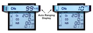
Can The GX-2012 Monitor 100% Volume Methane?
The GX-2012 can monitor 0 to 100% volume methane when equipped with RKI’s thermal conductivity sensor (TE-7561).If the GX-2012 is equipped with both catalytic bead and thermal conductivity sensors, it can monitor and display from0 to 100% LEL and 0 to 100% volume ranges of methane. The instruments display will show one line for the methanechannel and automatically change between % LEL and % volume ranges as the sample changes. There are no set upchanges or display mode changes needed.Also, to help hygienists quickly recognize if a worker has been exposed during a particular shift, the GX-2012 has aneasy to recognize graphical Peek Reading that can be seen in the normal operation mode. Without going to a differentscreen or pushing any buttons, a supervisor can quickly recognize if there has been any exposure for the worker whilethe instrument has been turned on.
Ordering Information for GX-2012 with 100% volume
72-0290-05-__ GX-2012, 1 sensor, % volume CH4 base, choose battery option
72-0290-11-__ GX-2012, 2 sensor, LEL / % volume CH4 base, choose battery option
72-0290-13-__ GX-2012, 2 sensor, O2 / % volume CH4 with alkaline battery pack
72-0290-18-__ GX-2012, 3 sensor, LEL / % volume CH4 / O2 base, choose battery option
72-0290-19-__ GX-2012, 3 sensor, LEL / % volume CH4 / CO base, choose battery option
72-0290-23-__ GX-2012, 4 sensor, LEL / % volume CH4 / O2 / CO base, choose battery option
72-0290-24-__ GX-2012, 4 sensor, LEL / % volume CH4 / O2 / H2S base, choose battery option
72-0290-27-__ GX-2012, 5 sensor, LEL / % volume CH4 / O2 / H2S / CO base, choose battery option
Add Battery Option letter below to the end of the Base Model part # and add price to the Base Model price.
A Alkaline battery pack only
B Alkaline and Li-Ion battery pack with 100-240 VAC Charger
C Li-Ion battery pack only with 100-240 VAC charger (Alkaline battery pack not included)
D Li-Ion battery pack only with 12 VDC charger (Alkaline battery pack not included)
E Alkaline and Li-Ion battery pack with 12 VDC Charger
F Li-Ion battery pack only with 100-240 VAC / 12 VDC Charger (Alkaline battery pack not included)
G Alkaline and Li-Ion battery pack with 100-240 VAC / 12 VDC charger
H Li-Ion battery pack only with no charger
What Is %LEL and %UEL
The primary risk associated with combustible gases and vapors is the possibility of explosions. Explosion, like fire, requires three elements: fuel, Oxygen, and an ignition source. Each combustible gas or vapor will ignite only within a specific range of fuel/Oxygen mixtures. Too little or too much gas will not ignite. These conditions are defined as the Lower Explosive
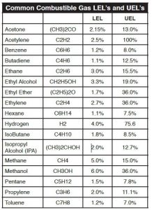
Limit (LEL) and the Upper Explosive Limit (UEL). Any amount of gas between the two limits is explosive. It is important to note that each gas has its own LEL and UEL, as shown in the chart below. The gas concentrations are shown by percent of total volume, with the balance as normal air.
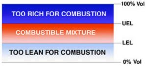
Between these two limits explosions can occur under some conditions, with the maximum explosive energy available at approximately the midpoint. Note that these limits are sometimes referred to as LFL (Lower Flammable Limit) and UFL (Upper Flammable Limit). These limits are empirically determined, and various authorities sometimes quote slightly different figures, based on slightly different experimental procedures.
What’s the difference between “Explosion Proof” & “Intrinsically Safe”
Electrical equipment sometimes must be installed in areas where combustible vapors and gases are used or may be present. These are commonly referred to as “hazardous locations”, and are defined by the National Electrical Code (NEC) in the US, or the Canadian Electrical Code (CEC) in Canada. When equipment must be installed in hazardous locations, there are strict requirements for the construction of the installation, including materials and design requirements. To prevent inadvertent ignition of flammable gases and vapors by electrical equipment, the two most common methods of protection are “Explosion Proof” and “Intrinsically Safe”. We will discuss these methods as they relate to gas detection equipment.
Explosion Proof
Generally speaking, “explosion proof” is the more commonly used method for detector/sensor assemblies for fixed gas detection systems, where higher voltages and power requirements may be encountered, and the installation is permanent. Intrinsically safe method can also be used for permanent installations where the detector/sensors are relatively low power devices. Almost all portable instruments use the “intrinsically safe” method. An “explosion proof “ classification for a sensor/transmitter means that the housing has been engineered and constructed to contain a flash or explosion. Such housings are usually made of cast aluminum or stainless steel and are of sufficient mass and strength to safely contain an explosion should flammable gases or vapors penetrate the housing and the internal electronics or wiring cause an ignition. The design must prevent any surface temperatures that could exceed the ignition temperature of the gases or vapors covered by its Group rating (see below). If the sensing element is a high-temperature device (e.g. Catalytic bead or “pellistor”), it may be protected by a flame arrestor to prevent the propagation of high temperature gases to the ambient atmosphere.
Intrinsically Safe
An “intrinsically safe” classification and design means that an electronic circuit and it’s wiring will not cause any sparking or arcing and cannot store sufficient energy to ignite a flammable gas or vapor, and cannot produce a surface temperature high enough to cause ignition. Such a design is not explosion proof, nor does it need to be. For permanent installations, such an installation may include “intrinsically safe barriers” that are located outside the hazardous location, and limit the amount of energy available to the device located in the hazardous area.
The North American classifications for hazardous locations as related to flammable gases and vapors:
Class I: Gases and vapors
Division 1: Gases or vapors are usually present and/or may be present at any time in sufficient concentrations for an explosion hazard.
Division 2: Gases or vapors are not normally present and are present only in the event of a leak in some kind of containment vessel or piping, again in potentially hazardous concentrations.
Groups A, B, C, D: Groups of atmospheres categorized by the volatility and/or ignition temperatures. “A” is the most hazardous and “D” is the least hazardous group for gases and vapors.
Group A: Atmospheres containing acetylene.
Group B: Atmospheres containing hydrogen or gases or vapors of equivalent hazard.
Group C: Atmospheres containing ethyl-ether vapors, ethylene, or cyclo-propane.
Group D: Atmospheres containing gasoline, hexane, naptha, benzene, butane, propane, alcohol, acetone, benzol, lacquer solvent vapors, or natural gas (methane).
What is the difference between Catalytic & Infrared?
Combustible Gas Detection
In detecting combustible gases in oil and gas, petrochemical and other applications, choosing between the two most common gas sensing technologies used for this purpose will be critical in ensuring a safe, reliable and cost effective solution. These technologies are catalytic combustion and infrared. Both have advantages and disadvantages depending on an application’s specific needs.
RKI Instruments, a world leader in gas detection equipment, offers both technologies, providing the user with flexibility in selecting the best sensing technology for their situation. Of the many hydrocarbons that are found in industry today, most are detectable with a catalytic combustion sensor and many are detectable with an infrared sensor. It is important to consider the specific compounds to be monitored as there are some that do not readily lend themselves to detection with a general purpose infrared (IR) detector, such as hydrogen, acetylene, and aromatic compounds, like benzene and toluene, for example. We will look at some common compounds and discuss the basic principles of operation for the two technologies as well as their advantages and disadvantages.
Catalytic Detectors
Catalytic detectors are based upon the principle that when gas oxidizes it produces heat, and the sensor converts the temperature change via a standard Wheatstone Bridge-type circuit to a sensor signal that is proportional to the gas concentration. The sensor components consist of a pair of heating coils (reference and active). The active element is embedded in a catalyst. The reaction takes place on the surface of the catalyst, with combustible gases reacting exothermically with oxygen in the air to raise its temperature. This results in a change of resistance.
Infrared Detectors
The Infrared (IR) detection method is based upon the absorption of infrared radiation at specific wavelengths as it passes through a volume of gas. Typically two infrared light sources and an infrared light detector measures the intensity of two different wavelengths, one at the absorption wavelength and one outside the absorption wavelength. If a gas intervenes between the source and the detector, the level of radiation falling on the detector is reduced. Gas concentration is determined by comparing the relative values between the two wavelengths. This is a dual beam infrared detector. Infrared gas detection is based upon the ability of some gases to absorb IR radiation. Many hydrocarbons absorb IR at approximately
3.4 micrometers and in this region H2O and CO2 are relatively transparent. As mentioned earlier, there are some hydrocarbons and other flammable gases that have poor or no response on a general purpose IR sensor. In addition to aromatics and acetylene, hydrogen, ammonia and carbon monoxide also cannot be detected using IR technology with general purpose sensors of 3.4 micron specifications.
Advantages
The major advantages of IR gas detectors:
• Immunity to contamination and poisoning.
• Consumables (source and detector) tend to outlast catalytic sensors.
• Can be calibrated less often than a catalytic detector.
• Ability to operate in the absence of oxygen or in enriched oxygen.
• Ability to operate in continuous presence of gas.
• Can perform more reliably in varying flowconditions.
• Even when flooded with gas, will continue to show high reading and sensor will not be damaged
• Able to detect at levels above 100 % LEL.
Disadvantages
The limiting factors in IR technology:
• The initial higher cost per point. IR detectors typically are more expensive than catalytic detectors at initial purchase.
• Higher spare parts cost.
• Gases that do not absorb IR energy (such as hydrogen) are not detectable.
• High humidity, dusty and/or corrosive field environments can increase IR detector maintenance costs.
• Temperature range for detector use is limited compared to catalytic detectors.
• May not perform well where multiple gases are present.
Conclusion
There is clear need for both IR and catalytic detectors in industry.
When making a choice, be sure to consider the field environment
and the variables in detector design. Life-cycle cost assumptions
will not hold true in all environments. The same can be said for
detector mean-time-to-repair or failure. Careful analysis of detectors,
suppliers and field experience will help you to select the best
catalytic or IR detectors for your application.
Why is the LEL important in combustible gas detection?
In environments with combustible gas hazards, it is important to know long before the gas concentration reaches the LEL. Typical safety standards require that a gas detection unit give warnings at 10 – 20% of the LEL. Do not confuse the alarm level with the volume of gas required to reach the LEL. For example: Methane has an LEL of 5% by volume in air. For a gas detector to give an alarm at 10% of the LEL, it must trigger when it detects 0.5% by volume. The detector for this application would most likely be calibrated for the range from 0% to 5% gas by volume, but display the reading as 0 – 100% LEL.